Special Notes:
1) In September 1997 we realized that the initial alignments of multiple gyros motoring themselves chaoticly cause a resistance anomoly in that the initial response to a powered displacement of the gryo plane(s) may be a mechanical demonstration of inertia -- at least the energy backfeed will cause wheel spin acceleration or ‘tumbling’/bumping in the precessional translation.
2) In March 1998 we found that combining:
A) a fixed in plane major arc;
B) powering precession and
C) fixing the wheel axis to a system that can force the major arc travel relative to an unconnected but fixed focal point; then the result is mass motion (that is not cyclical net zero motion).

1) Powered precession (helix or axial) for making position power (not negative resistance).
2) Mass (propelled) controlled/guided by: a rigid major arc plane that is established by:
a) A physical beam;
b) A curved track (rail);
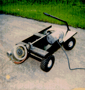
c) An outside steering mechanism (on ground or in fluid); -- as in (photo of) J-B cart
d) An inertialized system -- not accomplished satisfactorily yet.3) Resultant motion in major arc plane;
a) That is wavy;
b) That is linear (with free precessional rotation);
c) That is either continuous or oscillating.4) Continued (pulsed) motion by translated wheel plane(s) through the major arc radial line during the zero gyro periods (wheel plane parallel (or in)) the major arc plane.
5) Propelled mass is in the close vicinity of wheel(s) that basically have a long distance from the major arc torsion focal point; and a short (to zero) precessional arc radius.
6) The wheel spin and powered precession rate are coordinated for maximized rate of motion (power).
7) The inertialization of the arc focal point is accepted into the gyroscopic torque phenomenon so that the mass travel distance/period is maximized -- or controlled.
There are two basic velocity (vectors) in temporal time:
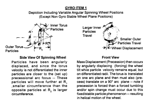
1) Spin - Arc motion combinations that are a gyro system (of at least two free (but physically or operationally linked together)) initiated by spin plane displacement that contains internal energies, and is made up of torus particles that are each bonded/linked or otherwise biased to a focal point: eg. a double gimballed spinning wheel...atoms, and planet systems.
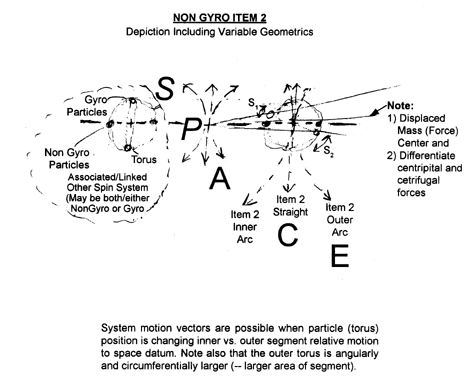
2) Essentially relatively straight non-gyro (-possibly associated with other systems) motion of a spinning mass sytem where the system is free to move non gyroscopicly parallel and/or in its spin plane with no spin plane angular displacement), but moving in a spatial datum (of reference); and is of essence arcuate -- by being in a stable arc motion or possibly by being subject to the torus speed differential (energy) of the spinning particles.
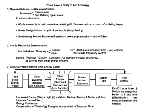
Items 1 and 2 of course are combinable for very complex arc motion geometrics that ultimately compose temporal time mass - motion systems. Being that one segment is faster and the other segment is at a slower (in Item 2) velocity, the speed of light (c) may then occur when either of the segmental stilling of its toroidal particles are at zero (in apogee) relative speed to the datum; and the opposite particles then move at some multiple of the total system (item 2) speed. One situation then being the torus is still spinning but there would be a holding of the segments so that the particles stay still as to a centroid (or in the case of atoms the electron would not rotate relative to the neutrons and possibly all the outer photons would be released). This sets up the phase change from mass matter to energy matter (eg. light) at this velocity the photons (and other energies) that shed (or are stopped) result in no vectoral (mass) force. (E = m = I = v = ma = gyro precession = hg = GF) while below this speed the atom (or molecule) is a combination of mass and motion (containing photons -- the energy of light is retained in the electron - photon combination); and is subject to the arc associated energy geometrics (gyroscopic action). Above this speed there is a relative reversal of spin -- for an energy phase change. The assumption is that the system components (particles of the torus) would be stable, regarding any 2 opposing particles, and they would have a bias to remain at their stablized linked velocities as to either items 1 or 2 (gyro vs. non-gyro motion).
PURPOSE
This report’s purpose is to journalize a science dialog of observations of gyroscopic actions in various system configurations; with specifically applied forces and the resulting (re)action(s). The scope of the report covers the demonstration apparatus used with some mechanical projections. Also, some intuited usages are proposed – particularly in the induced cyclic possibilities that would include inertialized enhancements for linear travel of a system that breaks through gravitational unity. Further, the scope is extended into both time-mass transfer properties possibilities, and the basis (orbit’s force theory) of mass formation – Also the mechanics of inertia may be gyroscopically demonstrated.
ABSTRACT
After the resistance anomaly, torsion is not only the keyword - it may well be the only word for the auto accommodating power transfer conversion from (singular and dual) torque inputs to a gyro (powered rotor wheel with & without powered prescession). There is a double-torque plane system that will multiply, and distribute output within 3 RPMs ratioed while accommodating the opposing load(s). These three RPMs need mass, speed/time, and power ratio development for practicable usages -- then there is the 4th dimension of powered precession that can move a gyro system -- and a 5th dimension that when precession is held in a plane that is controlled (powered) in sympathy with an oscillation frequency, as if powering precession, then wheel spin acceleration can be induced.
1. The wheel (the major spin plane) RPM (+mass).
2. Arcuate angular displacement of the major spin plane.
3. Arcuate angular precession in a plane 90° to the major arc plane.
4. Powering the rate of precession will feedback to the major arc radial.
5. Including the vehicle in the major arc element will serve to effect the motion of the vehicle.
6. Timing the passage of the wheel plane through the major arc radial during the parallel periods faciliates the efficiency of the motion -- but is not necessary for continuous motion as that can happen because of the torque efficiency differential and inertia when the mass stays in the same major arc.
There would also be time relative laws of mass transferring in a zero point torsion activity.
The real question...Is there a "free energy" amplification?...
This seems to have a simple two-letter answer...__ __!!But there is an in-space torsional traction that can be powered & inertially levered for linear motion. We may not (yet) achieve space (or antigravity) travel on inertially levered gyro propulsion; but we have gyro propulsion on certain terms and postioning. Newton’s Laws need some interpolation/extrapolation (at least a corollary) when it comes to mass spin energies/inertias transmittals of gyro power systems - or maybe even, hopefully, a fourth Law that allows spin time-power trades with mass repositioning; i.e. the drawing-in of nature’s basic orbits force system in the time-mass-motion spectrum through an arcuate based stable (spatial) force plane. This force plane appears to be given into arc motion as integratable into an helicly-based travelling torque system processing that can be defined/charted for power/motion outputs. These outputs can include wheel tumbling (motoring) or wheel(s) spin (motoring) -- possibly both happening together either naturally in a structure or by powering and natural (but guided) precession by forcing the precessional plane to follow a (naturally) desired path (and frequency).
The conservation of energy may be becoming a conceptual constraint because our energy scope is too narrow. The known time-motion-mass inter-relativities can only behave within our perspecality capabilities. The incapabilities to advancement can fall with less intellectual effort as more and more physics insights are broadened...
A) Slightly expanded understanding of the energy continuum?:
1) Time may be the carrier/disbursement means into motion and mass.
2) Time carries the origin energy.
3) Not all the origin energy goes from time to mass & motion.B) Expanded Further??:
1) The origin energy is composed in coloidal modulatings distributions that are never able to exceed the origins contents.
2) The orgins content is the imposition of arc (spin) and its gyro plane energy as a net energy allocation from a total of all energies available in temporal (mass & motion) time.C) Metaphyscial???"
1) Temporal time macro (energy compost) includes the original will (or plan) to differentialize itself into a micro of temporal time (-- or balanced opposing micros).
2) The plan energy executed of itself into a knowledge (power) metering.
3) The knowledge transmits by means of ‘temporal’ time energy flowing of ‘gyro’ (spin) energy formulated through: ether...light....and mass-motion "conservation of energy" can only be complete when all energy allotted into temporal time is accounted for, and the energy continuum is thus broadened.
These demonstrations may at least provide insights toward clearer understandings of a next era of gyro-inertial fields-involved power systems (including making ‘gravity’ and anti-gravity) - made up of compounded etheral: sub & atomic, molecular, mass (through all intra-galactic integrations) arc motions...also being the fundamental universe (mass/motion/energy) - forming basic!?
A GYRO IS...
• A many faceted, spatially-stabilized torque (orbital) geometrics phenomenon.
• An energy device that has a load-bearing, force-seeking, spatially-anchored stability reference.
• A double-torque plane system with many multiples of wheel weight power available as distributable from the powered major arc (wheel spin plane) to the free (arc) plane of precession.
• A two plane torque system that will sense the loadings, and distribute commensurate torque variable/self adjusting ratio(?gear?).
• A near to linear motion device when the precession arc of the wheel is powered and the major arc involved mass has momentum; and in which the torque action is pivotally ratioed and controlled (guided) so that the major arc plane is essentially flat.
• When in a cluster mounted assembly (with free single-plane centered gimballing), a motorization of one or more gyros occurs from precessional frequency communication of other gyros in the structure. The motoring may be wheel tumbling or spinning. Both actions are inertial in nature; but tumbling gets satisfied while wheel spin acceleration doesn’t get to a climax.
• A time-torque metering system.
• A strong tendency toward zero time wheel mass transfer action -- especially the bumping/’tumbling’ initial "motoring" or alignment reaction.
NOTES:
1. One arc can be powered and the other loaded, but mechanically linking the two motions will (virtually) cancel the wheel spin plane energy (unless the proper angular rates of major arc to precessional arc are discovered).
2. Structurally mounting and closely axially connecting two counter rotating gyros (virtually) cancels the gyro precessional energies - at least they are confined to within the structure.
3. There can be an extended precession reaction to very little angular major arc plane action when RPM: precession ratios are peaked - this is also cyclable and would be the propulsion/anti-gravity possibility that can track (be guided mechanically and otherwise) into nearly linear travel when a long (possibly induced) major arm radius is employed. The major arc plane angular (helical) displacement would be powered and of course, have multiple wheel assemblies on the same device. There appears to be inertially contrived single wheel cycling available -- or two balanced wheels, in the same plane and same rotation, made to reverse torque in timed switching of wheel planes from under to over major arc radius arm parallalism.
4. Conversely to note 3, forced precession power increases can increasingly, with higher major arc loading, extend the torque reaction time (period) fed back to the major wheel plane displacement rate - in other words, varying the powered precession can vary the time & weight (load carrying) and 4th dimension motion.
5. Allowing powered precession a full 360° turning reverses the major arc torsion every 180° (unless the wheel plane passes through the line of the major arc radial) -- the easiest time for this is when the axial/radial line of the precessional arc is 90° to the plane of the major arc. (Note: Try this when a wheel plane(s) not perpendicular to major arc radial.
6. One of the two angular wheel displacement planes must be essentially ‘free’ to precessionally react to the displacement of the other.
7. Nearly linear motion can occur when the precessional torsion system has powered ‘zero’ moment arm from the wheel plane to the total precessional mass inertial centroid axis, on a very long and single plane major arc radius.
8. Generally, the major arc is the most loaded or powered and the precessional arc is the least loaded or powered; or torus (helical) motion is included in the precessional arc motion.
9. Powering precession (back feeding energy) to the major arc has no ‘bumping’(motoring) and may be very efficient -- certainly more efficient than the opposite power flow (re: more power to major arc rotational than to minor arc rotation). Powering major arc vs. powering minor arc is causing negative inertial vs. causing positive power.
10. Small (seemingly no) major arc motion can produce extended minor precessional arc travel.
11. A gravity altering vortex (helical gyroscopic mass spin mode) can occur when the whirling mass is fluid - or particalized. The whirlpool (nature’s anti and augmented gravity weather-making device) is a rising or falling helix that may get its lift from an effective gyro fulcrum displacement, now known as coreolis force. This torus systemized motion is in reality many multiple associations of gyroscopic interplay. This of course is the complex arc-energy relationship that occurs in nature and in all probability is the basic building principle of energy as expressed in the time-motion-matter anomaly called gravity.
12. The back spin such as might be induced into the #10’s low and high pressure weather systems -- that are gyro systems with the major arc focus far out on the line of the earth’s axis (Note 1: That the northern southern direction is the line of wheel spin passage maintains motion towards the earth’s center combined with precessional "with" guidance by the earth’s surface and friction for precessional power and atmospheric depth for helix directional (vehicular) freedom. Note 2: That the weather low pressure spin is in the same rotational and system travel as water in the sink -- Also with the same wheel passage principle through the major arch radius (showed different systems) in different hemospheric have the same (downward) motion but with a reverse in angular rotation (visa versa for the high pressure systems -- and water spouts???)).
13. Planetary tilts and equinox passages could be induced spin power and orbital conditions of zero (or anti) gravity.
14. The plane of the wheel(s) positioning has a range seemingly from .00...1° to 89,999999....9° where it will have consistant behavior -- in other words the ‘passage’ can happen in a very small angular period, but will then keep the same torque characteristic for very nearly a full 90°.
WHAT GRAVITY IS ANECDOTE:
What if every electron in every atom in every mass on earth had a major arc deflection radius focused essentially below a tangential line from its position on the earth keeping it in an orbit system that is falling relative to a rotating radial from the earth’s center, with powered precession possibly inducted by the change of the spin axis of the earth’s rotation in a held plane while held (orbiting the earth’s center by the earth’s surface; with a system (vehicle) path biased towards the center of the earth (note this bias is really the seeking of a lower orbit as there really can be no direct travel by a ‘falling’ body towards the earths center - due simply to a body "falling" from a higher orbit (bigger circumference) to a smaller circumference, while maintaining a constant tangential speed).
The ‘above’ a tangential line major arc deflection focus would displace that system (vehicle) away from the earths gravitational system -- probably to associate with another gyro system ( it would take opposite spinning electrons to come back -- but that would be antimatter to earths matter ...bad, very bad).
(Sun orbit is a major arc focal point).
A GYRO IS NOT:
• A free going linear propulsion device without specific torque inertially fulcrumed arc-plane geometrics - the wheel cannot be gimballed in planes (in a straight line) that includes the center of gravity of the wheel, when guided precessional motion is intended; though its spatially stable torque properties still happen in this mounting configuration.
• A field communication device - but multiple gyros mounted on one structure will display intra-definitive sympathetic precessional spin harmonies.
• Capable of energy translation when there is no precessional (arc) travel, i.e. fixing the axis of the wheel into only one arc-travel plane will eliminate the gyroscopic torsion phenomenon.
• A free energy device; nor will it amplify input energy other than in an induced gear motor like ratioed input-output.
• A free (space) unguided lifting device - one end of the torque arm transmits the "lifted" weight through to a supporting (or inertialized) major arc force base -- but the torque arm can be focused to a distant point and it is possible to reverse the torque during the 90° wheel plane to major arc transition(s) -- producing pulsing but directionally planned arculate travel of a vehicle.
POWER/ACTIONS LISTING
1. Self-reactant variable torque - with & without projected (nonstructural) fulcrum points:
a. Major Arc force with:
1. Fixed arm (that entirely precesses).
2. Broken arm (major arc stays planar).
b. Precessional powered arc motion with free variably loaded major arm travel:
1. <180° rotation & single torsion direction of major arc.
2. 360° (Broken major arm) and two (opposite) direction each 180° of precessional (short arm) rotation.
3. #2 with timed wheel centroid passage thru major arc radius.
c. Ratioed torque (with varying geometry manipulations, and many multiples - gear motor like) of major arc force into minor arc (precessional torque. (NOTE: a 1¾ HP input to a 20 lb. Wheel can ‘snap’ a 5/8" diameter wheel shaft - in an instant after responding to a major arc torque loading.2. Continuous Lift - in major arc plane with the wheel at the fulcum point, and 360° precession - free travel - the lift can be increased and decreased by powering the precession -- note that the time of angular displacement is changed to accommodate the increased anit-gravity (lift).
3. Linear travel - in precessional axis plane:
a. With manipulated precession.
b. With inertially effected precession.4. Pump - in major arc plane:
a. With powered 360° precession.
b. Manipulated (oscillating) precession.5. Centrifugal/centripetal mass energy changes (cancellations - or potential energy accumulations?):
a. Fixed major arc:
1. Free precession has centrifugal force removed (relayed or delayed?).
2. Powered precession seems to delay centrifugal force, and transfer it to radial after reaching 90° wheel rotation dead gyro position.
b. Broken major arc:
1. 360° precession with torsionally modified centrifugal force during dynamic period, but an inertial surge linearly along the major arc radial during dead (parallel action) period.
6. A self-induced spin plane energy communication through its structure from one or more gyros to another; altering the precessional action from oscillation to rotation.2. 180° arc segments precession reversal of major arc direction under precession power.
7. An immediate (possible zero time-mass-motion) positioning to a gyro force canceling (90° axes planes) when free precession is allowed -- this is an opposing force back feed to the origin force for what may be a mechanical demonstration of inertia.
8. An immediate (possible zero time-mass-motion canceling?) cessation of precession when the major arc axis is unloaded.
9. Except for an initial (inertial line ) resistance precession is a reactionless (or may be timeless) torque activity.
10. A reversible polarizing (parallel axes direction finding) of a gimballed wheel group of gyros that are mounted on radial spokes and rotated -- moving through inertial into magnetics ( -- a transiting from power through inertia to magnetics).
Notes:
1. There are obviously many speed ratio rules to be ascertained.
2. Virtually all actions are gravity affected in some manner (a freely rotating/precessing wheel will adjust its rate of turn to the load, as as to orbit the load in a neutralized gravity plane).
3. A gyro force system may be the basics of mass-motion energy.
4. A gyro network (random assembly) may be demonstrating the mechanics of inertia (through magnetism; electricity...etc). The gyro is not so much space ‘traction’ -- as it is a torsional mass (inertia) handling ( -- as part of a reactionless torque system) and substituting motion energy for time/mass energy ( -- wants to be all (sublight) motion -- zero time arcs system translations). It is a (reactionless 90° tangential centroiod track transfer) satisfaction of randomly positioned multiple arc motion change energies in their precessional reaction. It doesn’t matter about the ‘wheel’ plane alignment to impose resistance that occurs initially as far at the overall work of precession is concerned. Inertia may be the chaos of mass gyro particles force planes displacement energies: 1) alignment (‘bump’ of spinning mass reaction to arc plane displacement) 2) precession as angular molecular/atomic force (d) precession is a mass realignment period to an arc change (force) which is either a timeless ‘wannabe’ or a distance less ‘wannbe’ -- all arcs displacement has available side effects of energy: ‘inertia’; motion, force (from torque), motoring of the wheel plane and the wheel itself.
NON-ACTIONS LISTING:
1. No gyroscopic activity (dead weight) when precession is prevented - or has its wheel plane motion in its same single plane.
2. No precession from a major arc displacement after minor arc motion reaches 90° to the major arc axis motion plane.
3. No activity when equal counter-rotating gyros are on the major arc axis - even if the major arc is essentially free in space.
4. No activity when major arc and minor arc are mechanically directly linked.
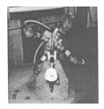
DEMONSTRATION HARDWARE SYNOPSIS:
11 manual/powered machines (also including 6 ‘toy’ gyros and 1 bicycle wheel), where all 3 RPMs are variable and reversible, air motor driven gyros with variable speed major wheel turn, and air motor or manual or free precession actions. The wheels vary in mass from 1.6 ot 19.6 lbs. The final two machines have guidance for linear precessional propulsion, both in horizontal and vertical (anti-gravity) directions. Multiple gyros in a structure to demonstrate gyro interplay.
DEMONSTRATIONS:
A. ‘4 - Spoke’
1. Description: 4 spokes with single-gimbal gyros on the outer end (‘satellites’) of each spoke - manual turn of assembly. Spokes are adjustable and pivotable; gyros can be held in various positions. (Free to translate on major axis; gyros mounted with gimbal axes 30° to spoke radii).
2. Purpose: an attempt to obtain linear action from rotation of the assembly.
3. Actions:
a. Uninduced but stable incessant rotation of one gyro, whose axis is nearly parallel in an easterly direction (a ‘moon’ if you will), and which seems to be caused by inertical (or alignment energy) frequency of the other 3 gyros self-induced disharmonious oscillation; this disharmony is not perfectly stable (irregular), and may be due to the possibility that the gyros are indeed (slightly!) off-center;
b. Also observable is a minuscule rotation/counter-rotation of the whole assembly;
c. the range of oscillation of the opposite gyro appears to be ‘corrective’ to maintain the full rotation of the opposing gyros power input changes.
d. we can manipulate the frequency and a much more rapid motorization of some/one/all of the gyros can be induced.
e. the above contains noticable resistance while the system is initially accelerated -- also the precessional ‘bumping’ that is an immediate response to any gyro rotation plane change appears to join in a power frequency oscillation that is transmitted to the other gyros in the system.
Note: This arrangement has the possibility for induced wheel spin acceleration as the plane of precession is controlled as to rotation of the wheel ("tumbling") plane can also rotate in a flat plane that can be wobbled in a helical swirl pattern.f. there is no linear motion of the assembly which was the original intent.
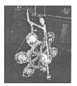
B. ‘6 - Satellite’
1. Description: 6-satellite single gimbal gyros on air motor powered major wheel hub; pendulum held assembly for either horizontal or vertical major wheel turning plane (pendulum) hung freely on a vertical cable that is motorized to raise and lower the assembly. 3 modes:
a. 6 satellites spin (natural and induced gimballing);
b. Major wheel spin, and satellites’ spin;
c. Major wheel spin without satellites’ spin.
2. Purpose: to observe the multiple arcuate travels that would possibly simulate atomic, molecular, solar, galactic arc-plane interchange possibilities on the satellites; and the assembly.
3. Actions: (satellites’ gyros spinning but major wheel not rotating):
a. ‘Communication’ between machine’s elements that causes various motor-like rotations of the satellites (gyros wheel plane rotation) in some form of sequence (the ones that ‘want’ to become motors seem to be in the same easterly axis as in the case of A;
b. When the whole assembly initiates spin in one direction, all the gyros face (polarize so that the gyro wheel plane is in the same plane of rotation as this assembly - or if a rotation of the plane of the assembly occur, then they settle at the helix angle of the track of the satellites), the same way immediately and all at once. Likewise, when the whole assembly is spun in the opposite direction the gyros behave the same way, except that they face the exact opposite direction (parallel axes of major and minor wheels);
c. Self-induced or manual oscillations of the entire assembly will motorize self-selected satellites in a selected direction of rotation depending on the half initialization cycle;
d. When we add putting the whole moving assembly into an (third) arc motion (in an arc via a cable attached to the ceiling), chaotic displacement of the system occurs.
4. Interpretations: (a) when an additional arc motion is imposed on the fully active assembly an apparent induction of tangential motion occurs that rotates the wheel plane of the planetary gyros -- this appears to be an ‘origin’ of planetary (& electron) rotation around a focal point that is established spatially. In other words planetary orbiting motion is induced by the earths precessional spin and the system displacement (solar system forces motion) around the sun is being affected by another associated arc motion. This tilt also relates to another third reaction -- the whole system is in a 2nd helix track. Also there is a ‘motor’ frequency involved -- possibly being indicated by the changing 21° (now) tilt axis. Note that the wheel planes (of: the sun and planets, and their porations) are very nearly in the same plane. (b) Once the precessional spin alignments, begin which is a highly resistive period of oscillation, then instead of settling down in a fully stabilized amalgam various oscillations and ‘motorings’ occur, and a shifting from motoring to oscillating continues to occur in a self induced manner -- possibly from other arc planes displacement from outer planet: solar, galactic...etc. arcs/displacements-- along with internal molecular atomic...etc. arc plane displacements. (c) Try to keep in mind that there could be a virtually endless compouning of ‘spokes’ on wheels that are a systems that are spokes on wheels that are spokes in wheels...ad infinatum.
This leads to: inertia, magnets, electric...etc. Phenomenae: First, there is the irregular (bumping) initial reaction that imposes resistance to the major arc plane energy (from ‘input’) that will be instantaneous gyro particles’ alignments transitioning to a steady load carrying precessional continuation of the major arc plane displacement. Second, there can be a ‘motoring’ continuously rotating in response to erratic (but systematic) major arc plane displacement, (or) third, there will be a reversing of the precessional alignment if the ‘erratic’ frequency of major arc displacement that can be so timed for motoring (or oscillion) as is seen in the ‘pump’ action mechanism. All these are to be very likely the basic mechanics of inertia.
The ‘bumping’ has been observed in gyroscopic initial reaction, and has been seen as an obstruction to the smooth major arc displacement energy transfer into precessional motion/torque. This period of resistance (until smooth accommodation into a new precessional stability) appears to be a time energy torque re-establishment relativity indiginant in the mass arc travel inscription of (into) an associated energy plane. Rotational dislocation of this plane re-establishes the mass spin into another torque field that is a helix axis 90° torus of precession. This can be load bearing and the final satisfied rate of precession that is very power capable (almost limitless power torque reaction) is gained after the ‘bump’ period. When the torque is passing through the alignment period that opposes the processing (the "Bump"), the cost of input energy buys acceleration of the system (mass). This is looking at one "gyro particle" activity. When many gyro particles are in structure and, of course, at random positions, the sum of the "bumpings" becomes "inertia".
All these "bumpings" have a time mass energy relativity that is an associated torque amalgam of realignments. (When these realignments become parallel axises, then the system becomes magnetic.) When the magnetic system re-associates into a rotating plane of prealigned parallel systems, then the field (energy plane) will become an energy field (in a structure) that will self-communicate as "electricity".
The "structured" connection is inertia and the "motoring" frequency of bumpings can occur. This is another way of interpreting the shift from oscillation to continuous rotation of a communication from one acceleration processing to another "structurally" connected processing. This seems to occur similarly in electrons, atoms, molecules and mass (associations) and on through the spectrum...radio; radiation; (?light...time?).
The above is also meant to say (somehow) that strong limitless speed motion (vehicle) is available; and that the "bumping" is the inertia phenomenon basis. It is an attempted zero time realignment of the precessional (response) to energy input into a satisfied stability mode of an existing mass-time-motion-(powers) relativity.
An out of mass bumping tends towards instantaneous acceleration between the upper and lower mass motion time fringes of existences of mass motion energies.
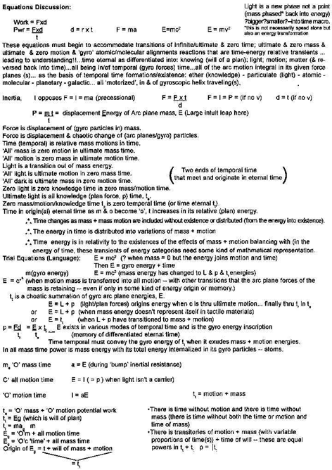
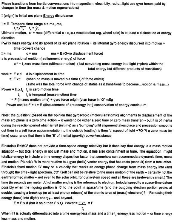
C. ‘Gyro-Dolly’
1. Description: two 1.6-lb. air motor driven gyros, multi-positionable, opposed mounted, spring loaded on swivel mounts and attached to a rotating (air motor driven) bar - the entire apparatus is placed on a ball-wheel platform that is free to move in any direction. Average gyro speed here is 3000 RPM on ½ HP air motors. Spring attachments are variable in the plane of precession.
2. Purpose: to observe horizontal motion on a smooth surface.
3. Actions:
a. Barely recognizable (very poor!) linear motion on the floor;
b. Oscillating action in a curved direction.
4. Interpretations: this is what is known as a bust. No further investigation of this device is intended at the present time.
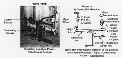
D.-A. ‘Gyro-Pump’
1. Description: one or two 1.6 lb. gyros drive by ½ HP air motors (assembly) on a fixed mount base. Manually and free precession operated rocker arm (optionally spring loaded). Two rotatable platform (One shown) mounted gyros and two rocker configurations (single or double plane rocker action).
a. Single gyro with 6" R. (precession) turn axis perpendicular to rocker arm (at outer end) and (a) free turning, and manual turn (oscillating), linked (forced) recession oscillation to rocker arm action and (d) powered precession – 360-° rotation.2. Purpose: To observe single and multiple wheel’s action on a basically fully free swiveling system with manual and mechanical inputs into the major arc and precessional arc rates.b. Single and double gyros (2nd similar ½ HP, 3000 RPM air motor powered, 1.6 lb. Gyro mounted at opposite end of the 3’ long rocker arm). Modes: (a) both free precession; (b) one gyro with powered precession 2nd free; (c) one with powered precession and one precession linkaged to major arc action – spring set loading optionally applied.
c. All of the above on a 2-plane swivel mounting of major arc arm.
3. Actions:
a. (Free turning) very many and variable responses to powering major/minor arc including increased weightlifting capacity when precession is accelerated;
b. (Linkage) none – the linkage, even though it was highly variable did not find (or allow) the desired result (major arc torque control);
c. (Power) very positive action, i.e. the first 180° of precession would force the arm one way, and the second 180° of continued rotation would power the major arm in the opposite direction;
d. Full 360° cycle would be two-way pump action capable of lifting many multiples of wheel weight. A very short precessional arm would still provide vigorous action – even when the wheel mass was directly over the powered precessional pivot.
e. Two gyro’s mounted on powered precession appeared to double the power if not in incompatable spin/location disharmony.Notes:
1. This is a reactionless (that is no torque is transmitted to or from the structure by gyro power).
2. Powered precession introduces a fourth permeter/dimension for wheel spin; major arc inputted; precessional arc and major arc output with powered precession.
3. When the precession is powered and the major arc planes are appropriately controlled spin energy can be induced back into turning only the gyro wheels.4. Interpretations: This device looks to be a useful mechanical power device as the pumping action could accommodate increased loadings automatically. This set up can also act as an open beam crank engine.
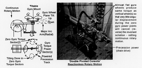
D.-B. Double Pivoted Coreolis (Same Mounting Assembly As Gyro Pump)
1. Description: Same mounting wheels and motor, and pivot beam but with a double gyro assembly on a powered pivoted yoke on (both or) one end of the major arc beam, that permits the two single plane gyros to pass through the major arc radial line (parallel to the physical beam) when in powered precession.
2. Purpose:
A) To obtain continuous arc motion by oscillating the gyros as they pass through the no gyro power -- (wheels spin energy effectively parallel to the plane of the major arc plane) positions twice in each full 360° precessional turn; and
B) To find if this geometrics can be imposed into a vehicle for substantially linear travel.
3. Actions:
A) There is a vigorous pumping if there is no passage of the plane of the gyros through the radial line of the major arc during the no gyro power sector traverse.
B) the reversal (pumping) will not occur if the passage is accomplished -- so the major arc motion will become a continuously unidirectional rotary motion.
Note: The design can be compacted into a spoked radial configuration.
4. Interpretations:
A) It appears that this pulsing continuous action can be applied to a vehicle (such as J-B);
B) The plane passage requires only overcoming the small inertial resistance of the pivoting mass -- only during the no gyro positions -- this can be done by angular momentum or one of the radial forces,
C) The flat (perpendicular to the major arc plane) wheel position as opposed to the vertical wheel make no action difference as to torque output;
D) There may only be a minute angular change of alignment with the major arc radial to effect the torque reversal (from powered precession);
E) The so called coreolis force change from the northern hemisphere to the southern hemisphere appears to have the same geometric gyro characteristics as seen in spiraling water going down a drain -- or even more interesting is the reversed weather spirals of lows and highs that move down and up in the northern vs. southern hemisphere. The planes of the spin are passing through the spin axis of the earth while the weather is being forced precessionally by surface friction with the earth. The weather has depth (of atmosphere) which is the major arc motion of the system I don’t know why the radial line is pointed along the earth’s radial line, but the tilt of the earth may figure into the spiral of the earth sun rotational plane helixing axially with the galactic system.
5. Special Note: This mechanism produces torque that is one way power, no equal & opposite (re)action -- rotary power with no reaction (at least not in the plane of rotation).
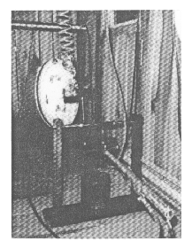
E. ‘Moon-Wheel’
1. Description: a 20-lb. wheel on 1¾ HP air motor configured on single or double (rocker) arms. 60" long rocker with linear free horizontal slide (90° to rocker action) optional. Also, a manually precessable (rotating) rocker (major arc) end mount alternative with adjustable precess radius - assembly mounted on fixed base.
a. Mode 1
i. Single swivel plane rocker and fixed gyro,
ii. ‘i.’ with linear slide (optional).
b. Mode 2i. Single swivel plane rocker with broken precess pivot arm (12" from end of rocker arm),
ii. ‘i.’ with linear slide (optional).
c. Mode 3
i. Double swivel plane rocker and fixed gyro,
ii. ‘i.’ with linear slide (optional).
d. Mode 4
i. Double swivel plane rocker and broken precess pivot arm,
ii. ‘i.’ with linear slide (optional).
e. Mode 5
i. Single swivel plane rocker with gyro mounted on 360° swivel,
ii. ‘i.’ with linear slide (optional).
f. Mode 6
i. Double swivel plane rocker with gyro mounted on 360° swivel,
Modes 5 & 6 are rigged to lift extra weight with forced precession applied.ii. ‘i.’ with linear slide (optional).
2. Purpose: same as D with heavier wheel and thus more forces involved and a linear travel possibility; also to observe the mass transfer of the wheel effect.
3. Actions:
a. Very strong torque (over 400 ft-lbs) resulted in snapping a 5/8" shaft;
b. centrifugally, the wheel apparently moves through a sector with a modification or at least a transfer of the centrifugal force action to the next sector 90° (wheel parallel to the major arc plane where a lateral centripetal surge along the major arc plane occurred;
c. A linear action occurred when another swivel plane (lateral) was added to the major and precessional minor arc swivels;
d. Manually powered single or broken major arm precession could cause many multiples of wheel weight major arc torque lifting;
e. Various fulcrum positions demonstrated specific time rate weight lifting ratios that need further experiments to determine;
f. When the precession fixing attempt was made, very small motion still occurred and again produced over 400 ft-lbs. of precessional torque;
g. Breaking the major arc at the tip for free 360° precessional rotation allows for much more machine work versatility;
h. Motorization of the precession alone can be made to happen by pumping the major arc as required;
i. When spinning the non-rotating wheel assembly, the centrifugal normal display does not occur when the wheel is spinning.
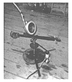
F. ‘GyroLift-Rig’
1. Description: a 7-lb. wheel on ½ HP air motor fixed to free major arc vertical plane (on a horizontal pivot with wheel mass set directly in the center of the precessional arc, 1/3 HP air gear motor driven the precessional arc about a vertical axis - adjustable counterbalancing/weighting - with a mounting option for observing centrifugal/centripetal forces (not shown)).
2. Purpose: to show the variable torque arm emanating from a zero travel (but pivoting) precessional action; also the lifting capability is faithfully controlled by the precessional spin rate.
3. Action: a 7-lb. wheel in slower range powered precession with major arc freedom exerted over 50 ft-lbs. of torque back into the major arc/arm for lifting/counterbalancing or other work applications.
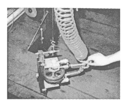
G. ‘Double-Wheel’
1. Description: a double wheel, counter directionally spinning gyro set - 1.6 lb. on each ½ HP air motor, gyro alternative (possible free mass transfer configuration), hung freely on a cable with a scale in the cable and the period of swing set to equal the weight of the two-wheels.
2. Purpose: to find free (reduced centrifugal force) mass transfer of double spinning gyros.
3. Actions:
a. No measurable reduction in centrifugal force;
b. The gyro phenomenon appeared to be canceled -- into structure stress.
Note: when the two gyro wheels were counter-rotating but hanging independently and still there was a measurable repulsion of the two wheels, but this was due to aerodynamics.c. One wheel had three (out of four) spoke breaks -- apparently due to internal structural stress
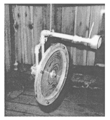
H. ‘Flywheel’
1. Description: a 1¾ HP 2500 RPM 16 lb. single gyro hung from a cable pulley pendulum.
2. Purpose: to determine a coreolis change in the gravity of the spinning wheel that is pointed in the direction of rotation of the earth so that the top half is rotating with; and the bottom half back from the spin of the earth.
3. Action: Indecipherable measurement.
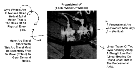
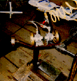
I. Guided ‘Propulsion’
1. Description: one (or two) 1.6 lb. wheel on ½ HP air motor, spinning in the same direction, fixed to free swinging horizontal plane major arc (that is manually assisted rotation) with a vertical, powered precessional arc pivoting that (assembly), is free to travel (linearly)) along a horizontal axis - with the mass center of the wheel located on a very short moment arm with a much longer (inertially loaded) opposite arm. The precession action about the linear direction axis. The major arc bar is in an arc pivoting as the assembly traverse but must helicly follow the linear shaft -- various inertial/counter force placements are possible.
2. Purpose: to show/find that a gyro can be made to travel linearly with powered precessional arc rotation and free-swinging but controlled/inertialized major arc swing system -- the assembly then will have gyro forced linear motion along a guided or controlled path that can be straight (with surprisingly small major arc pivoting) or on a curved path that supplies the major arc displacement.
3. Actions: a sideways traveling major arc, whose action also moves within the precessional plane of rotation; forming a helical complex between major arc and precessional arc that results in linear travel of the assembly in a composite of both planes -- but only during the period of the precessional arc that is gyro power active (wheel plane not parallel to the line of travel).
Notes:
a. This of course is the helix found in the swirl origins of planet/mass (particles) formation that ends up in the satellite planetary motion, and the planets ultimate spin in the direction and plane of its origin’s swirl.
b. The acceleration of this system appears infinite and it is a moving space traction (reactionless) phenomenon.
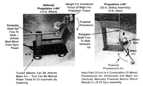
J. Horizontal & Vertical Propulsion
J.-A. Gyro Assembly (Motor Wheel, Arms, Piping...Etc.) Travel horizontal on a wheeled vehicle; and horizontal and vertical on a journalled shaft.
1. Description: a high ‘goodness’ 12-lb. wheel on a 1¾ HP air motor mounted as a linear travel assembly similar to ‘I’.
2. Purpose: to find horizontal motion and over unity anti-gravity (vertical motion) power.
3. Actions: a horizontal, torque induced, travel, similar to I occured. Approximately ¾" pulse of spatial traction torus lift (of 50-lb. assembly). This precessional lift was induced by the interplayed helix-like motion that was manually powered to the long precession arm -- although an attempt was made to avoid a ground based lever arm weight carry transfer we believe some torque transfer occurred.
4. Notes:
a. The inertial resistance imposed in ‘I’ and ‘J’ was done manually and took considerable action of the arm.
b. During the experiment, the wheel ripped itself loose from six ¼" diameter well-impregnated welds.
c. Coordination of forced precession and ‘turning’ of major arc rate to gyro demand ratio is essential to obtain maximized travel of asssembly.
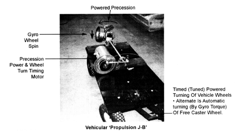
J.-B. Vehicular Travel
1. Description: Same as J-A except precessional spin was powered and mounted on the end of a journal mounted shaft); and the vehicle itself was the major arc travel by turning (steering) the wheels to provide the gyro torque arc -- finally timing the wheel steering with the major arc cycles -- or by a free castering wheel that turned in response to the gyro torque.
2. Purpose: To obtain vehicular travel.
3. Action: Pulsating and wavy travel obtained.Note: This type propulsion utilizes both gyro torque and a torque motion medium -- in this case wheel friction -- other possiblilities are boat ‘fish tailing’ -- or sail ‘fish tailing’.
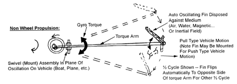
J.-C;-D-...etc.
When the major arc plane is held rigid (in its system), and the minor arc (precession) is both powered out free to backfeed into ‘tumbling’ or wheel spin -- a choosing of the gyro travel geometry) also a distant major arc focal (fulcrum) point is established either by a real or induced arm/beam then vehicular travel is obtained. eg; a roller coaster (J.D); or a rocket launcher (j.e); or a railway (j.-f); ...etc.
GYRO LAWS NEEDED (Speed - Loading - Time Integrations - Ratios):
SPEED RATIOS:
1) Free Accommodation: Wheel RPM/mass; major arc angular: minor arc angular.
2) Force Of Precession; major arc angular: minor arc angular and major arc liftingLOADING/POWER DISTRIBUTION RATIOS:
Major arc load: minor arc power; or major arc power: minor arc load.TIME DISTRIBUTION RATIOS:
Wheel RPM; major arc angular; minor arc angular and helix translation.4th, 5th & Possibly 6th Dimensions
Lifting by force of precession, travel by placing vehicle in major arch mass and back powering (motoring) either wheel spin and/or rotation/tumbling -- note there seems to be inertial type resistance in the tumbling mode reaction with or without back feeding wheel spin acceleration.
UNIVERSE ORIGIN ANECDOTE:
We struggle for (and against) a beginnings logic, within which apparently (so far, at least) we have no intellectual linkage available to jump backwards from being to pre-being. Most theorists seem to be groping from a time-field (that we are in) to some pre-time (eternal) situation. Our presumption is that the time eternal static (which holds the plan + the force of plan*execution) when made into time temporal through a knowledge force ether; then progressing into the motion-mass spectrum might be simplistically viewed in the splitting differential or opposing "micro-potentialities" from a relatively "static macro". So the origin would be the splitting of an arcuately set time micros from the eternal time static. Then a condensing into a pre-mass-motional-time intelligenced either through light (or separate knowledge) ‘waves’; then particalized ‘remembrances’ of an arc-energy origin into the motion mass-amalgam (...that may have a return ticket back through motion into light ...reversing knowledge, finally, back into the macro static).* Gyro relative forces extrapolations seem to be a lead into understandings for a universe ‘beingness origins’ force.
(PS - in this document we did not delve into orbitings of energy as imposed to differentiate mass formations into varying materials characteristics.)
*This is distribution/expansion and then returning/contracting back to the origin ... as opposed to going from all knowledge/motion time or continuing condensing/spending temporal energies until zero motion (all mass) time.
There may be a conservation of total temporal time energy but partials can only be indefinite percentages in atomic mechanics arrangements that are basically a simplistic arc spin phenomenon; that becomes at this point incomprehensible in its compounding of orbits, speed and gyro displacement ratios...or other energy compendium of time = mass & motion and ether energy (but when mass or motion goes to zero, time doesn’t. It absorbs the deficit to transfer into the torus of time; or If all goes to space relative zero the torus of time is then static.)
The torus particle radii displacement which is a replacement of the particles into a different orbit that carries a system into establishment of a new centroid location of the particle couplings (all new) orbiting situation...reactionlessly creating a new motion system because the particles are establishing a differentiation in a sub orbiting system which gyroscopically moves the entire original system... an electron (energy torus that can accept and reject photons) that is a rotating atomic mechanical energy rim that is at the speed of light and is "matter" when its atomic mechanical embodiment is in a motion -mass combo that is in relative (the real relativity) in-system speed range up to the electron rim speed. Then the advancing half circumference is at 2x "light" speed and the retrograde half is at relative zero velocity to the datum ("speed of light" and photon rejection) occurs making "light" as a phase change of matter energy into and beyond this electron speed-matter system atoms-molecules limit (or relativity). Atomics mechanics of motion-matter exists in this so called speed of light system and particle of atoms coupling.
TIME + MASS + MOTION (? + A TIME * ENTROPY?)
Photon - Light energy (the next energy in a spectrum before the integral of temporal time) input into the creation of the electron torus is the consecutive energy that moves the torus in its time mass motion energy transitions that comprise the existence continuum in a time mass motion oscillation (jumping the oscillation term might get back into time energy.) When precession goes to neutral period no particle radii differentiation occurs. It has reached a static response. Inertia is terminated. The differential orbits don’t change, and inertia no longer happens. A new focus must be adopted for the system. To precessionally energize movements in time+mass+motion helix oscillation by shift in gyro neutral moment (period) may occur in natural time+mass+motion; and may be retraceable by oscillation back tracking the precession of motion and or time and or mass energy.
Back track of interconsecutive arcs back into spin... (but if spin is not gained) then possibly arcuate backtrack into time. The return of mass-motion into time by reversing the time (not mass-motion) precessional track by replacing the atomic torus particles exactly through where/how they came. Is this mechanically possible? Is it a time relative process, or is it only a current time mass-motion relativity process?? Is there any such thing as current time-mass-motion in a historic continuum (the only real total energy conservation datum)?
* Another energy form in times content would be knowledge (the plan as an energy germinating entropic); and its metering into usefulness (evolution entropy deposits). The time entropy would be knowledge conversions by both evolutions in nature and mans workings.
Back to main page "Time"
Back to main page "Gravity"